 |
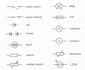
Circuit Symbols
 Some of the more common symbols used are shown.
This is not exhaustive – add others….
Some of the more common symbols used are shown.
This is not exhaustive – add others….
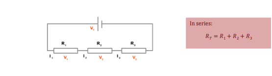
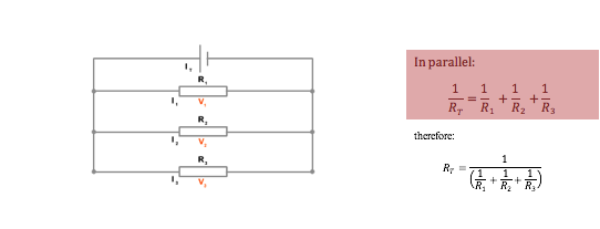
Combining
Resistances
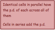
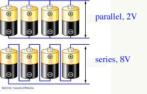
Combining Cells

Circuit Rules (Kirchoffs Laws)
This section is about understanding the p.d. and current in any part of any circuit. It involves the logical application of rules and problem solving more complex circuits.
1. The sum of the currents flowing into any junction is equal to the sum of the currents flowing out
This arises from the conservation of charge – no charge can be lost from the circuit.
 Mathematically this can
be written:
Mathematically this can
be written:
Important implications include:
- Current can be measured at any point in a series circuit and give the same result
-
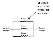
![]() At a junction in a circuit,
current splits in proportion to the resistance in each branch
At a junction in a circuit,
current splits in proportion to the resistance in each branch
e.g. In the diagram on the right, the current splits into proportions dependent on the resistors.
 The values of each resistor can therefore be found
using : R =
V/I
The values of each resistor can therefore be found
using : R =
V/I
= 6/8 = 0.8 Ω
= 6/3 = 2.0 Ω
= 6/5 = 1.2 Ω
2. In any loop of a circuit, the sum of e.m.f.’s is equal to the sum of the voltage drops
This arises from the conservation of energy – any e.m.f. (_) provided from a cell must be lost in p.d. (V) across the components in the circuit. Using V=IR, mathematically this becomes:
 Important implications
include:
Important implications
include:
- P.d. is always measured by a voltmeter in parallel
- The p.d. across different parallel branches of a circuit is always the same
- For circuit components in series, the total p.d. is the sum of the p.d. across each branch
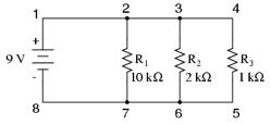
e.g. In the diagram the p.d. across each branch of the parallel circuit is 9V. Therefore the current the current flowing through each resistor is found using I = V/R:
= 9/10,000 = 9.0 x 10⁻⁴A
= 9/2000 = 4.5 x 10⁻³A
= 9/1000 = 9.0 x 10⁻³A
Internal Resistance
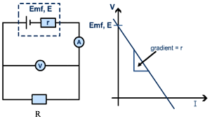
Up until now, we have thought of cells as being sources of e.m.f. with no resistance of their own. This is not true – current is impeded as it flows through a cell leading to internal resistance, r.
We consider a cell to produce an e.m.f., _ . Therefore the actual p.d. measured across the terminals of the cell must be less than this because it requires some energy for the charges to pass through the cell itself. This measured p.d. is called the terminal p.d., and the ‘lost’ p.d. depends on the internal resistance of the cell, so we think of it in terms of V=IR – in this case V=Ir as it is the internal resistance.
Terminal p.d. = e.m.f – p.d. ‘lost’ through internal resistance
V = _ - Ir
More usually this is written as:
Where:
_ = e.m.f. of the cell, V
I = current, A
r = internal resistance of the cell, Ω
R = external resistance in the circuit, Ω

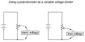
Potential Dividers
· Converts a difference in resistance into a difference in p.d.
· Are made using two resistors or a potentiometer
·
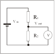
Allows a variable p.d. to be
supplied from 0V to the p.d. of the cell
·
 Used in sensor circuits (e.g. with
thermistor or L.D.R.)
Used in sensor circuits (e.g. with
thermistor or L.D.R.)
 |
|||